The ICONIX Business Modeling Roadmap - Version 2
Doug Rosenberg
ICONIX Software Engineering, Inc.
Based on our experience in helping a number of business process engineering projects over the last few years, we developed the ICONIX Business Modeling Roadmap; a set of activity diagrams which detail our simplified approach to business modeling. You can browse the Roadmap interactively here.
We
developed our initial Business Modeling Roadmap because business process
engineering efforts are a precursor to software system design, and there is a
natural desire to maximize commonality between the business modeling process
and the software design process which will subsequently be followed, (usually ICONIX Process for Software).
The
Virginia Department of Motor Vehicles has made extensive use of Version 1 of
the ICONIX Business Modeling Roadmap. You can view an HTML report of the
Virginia DMV Systems Redesign model built using the Enterprise
Architect tool, and read a case
study of the project on the Sparx Systems website. The DMV model is very large but is
still a "work-in-progress." It represents the combined effort of a
team of more than thirty dedicated professionals, all working together in one
model, with one goal: an effective new system for the DMV to support
its full range of internal and customer support activities.
Version
2 of the ICONIX Roadmap incorporates two new advances in technology that have
recently been developed, which enable for the first time the generation
of algorithmic code for business rules, starting from a natural language
description of the business scenario. These advances are the Business
Rule Composer from Sparx Systems, in combination with the natural language
capabilities of Raven.
This
article describes how these two advances in technology combine synergistically
to enable a new process.
Similarities and differences between software design and business modeling
ICONIX has extensive experience in
modeling software projects, and we formulated a compatible strategy for
effective business modeling that transitions seamlessly into software
design. In order to explain this
strategy, it's important to understand what's similar and what's different
between these two endeavors.
Business modeling and software design are similar in a number of ways; to begin with both business processes and software designs
are best understood by modeling scenarios . In both cases,
the scenarios that are identified exist to accomplish (realize) requirements,
which can be either functional or non-functional requirements. Some of the functional requirements
represent Business Rules.
Also
in both software and business models, an unambiguous vocabulary which describes
the important “things” (entities) in the problem domain is very
desirable to avoid ambiguity in the scenario descriptions. And in both
cases, first-draft scenarios typically get elaborated with a
diagrammatic representation of the scenario.
Business modeling and software designs are different in a number of ways; software scenarios (more commonly referred to as use
cases) typically involve one or more users interacting with a software system,
while business scenarios typically involve a mix of human-computer and
human-human interactions, where the human-computer interactions may span
multiple software systems.
Business scenarios are often modeled in both “as-is” (existing business) and
“to-be” (future business) forms, and it is especially important that business
scenarios are well understood by non-technical Subject Matter Experts (SMEs)
who understand what the business is about but may not be involved in Information
Technology at all.
Software scenarios in ICONIX Process need to be linked to objects, and also to
screens and GUI storyboards - business scenarios do not. Elaborating
software use cases with robustness diagrams forces those linkages, and is thus
the step we use in ICONIX Process for Software to disambiguate the use cases
prior to doing detailed design on sequence diagrams. There is a learning
curve associated with the robustness diagram notation (boundary, control,
entity stereotypes) which is easily justified for software designers but is
less easily justified for business modeling, which inevitably involves
non-technical SMEs. As a result the ICONIX Business Modeling Roadmap
specifies that business scenarios should be elaborated with activity diagrams
(which are more easily understood by non-technical SMEs) instead of robustness
diagrams.
Roadmap Overview
The
Roadmap consists of four major activities: modeling business process
scenarios , identifying requirements (and allocating them
to the business scenarios), modeling the problem domain , and
subsequently identifying software scenarios so that the new
business processes can be automated.
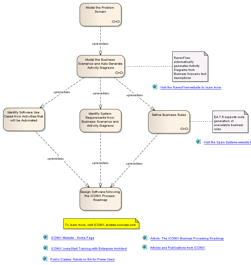
Figure 1. ICONIX Business Roadmap Top Level Activities
Requirements Capture and Allocation
We
use Requirement Diagrams to capture and organize Requirements .
The Roadmap identifies four specific categories of requirements: Functional , Non-Functional , Business Rules , and Data
Requirements . However, these categories are simply meant as
guidelines; feel free to group your requirements into whatever categories make
sense for your business.
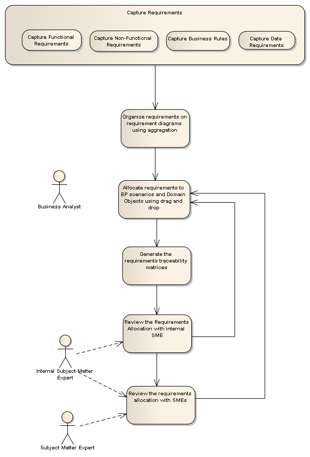
Figure 2. Requirements Capture and Allocation Activies
Note
that our Roadmap specifies both an “internal” Subject Matter Expert (this
is someone within the Business Analyst team who is knowledgeable about the
relevant part of the business) as well as the “real” Subject Matter
Expert , who is typically part of the operational business as opposed
to a member of the IT staff.
Also
note that the Roadmap specifies that Requirements, once identified, should be allocated to the business scenarios, and that traceability matrices should
be generated and reviewed. We have found that the Enterprise Architect (EA)
modeling tool does a remarkably good job at automating these activities.
Requirements can be allocated to scenarios using a simple drag-and-drop, and
EA's built-in relationship matrix takes all the pain out of generating the
traceability reports. Allocating and tracing requirements is critically
important to verifying the integrity of the business process models.
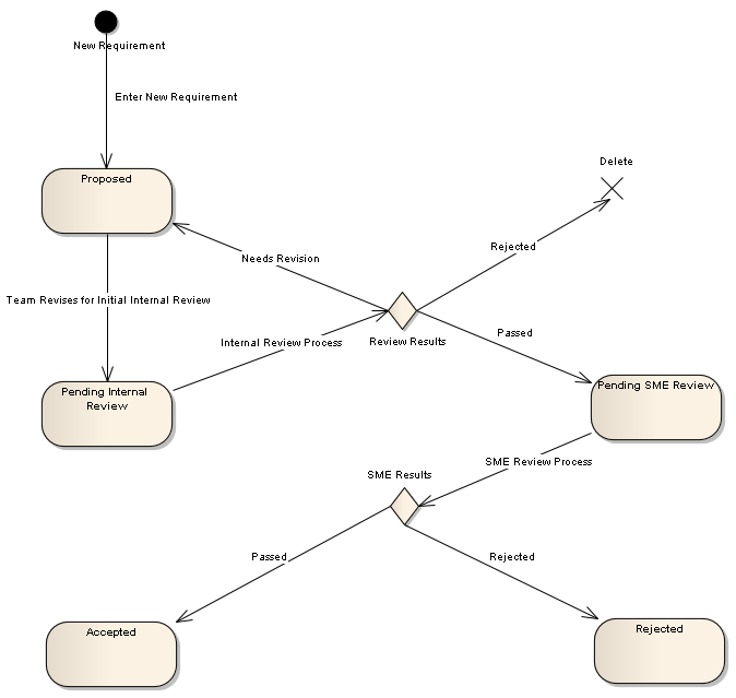
Figure 3. Requirements are
accepted or rejected based on SME Review
Modeling the Problem Domain
As
with our software design process (standard ICONIX Process), disambiguation is of fundamental importance in the ICONIX approach to Business
Modeling.
Ambiguity
in specifications (whether they are at the business scenario or at the software
scenario level) often starts with analysts using multiple names for the same
“problem domain entity”. Therefore the same guidance that we provide in the
ICONIX Process Roadmap applies in our business modeling roadmap.
Business
Process Scenarios should refer to entities in the problem domain unambiguously,
using a well-defined and documented name. We show these entities on a domain
model diagram (a simplified UML class diagram) which shows the entities along
with the “has” and “is” relationships (aka aggregation and generalization)
between them.
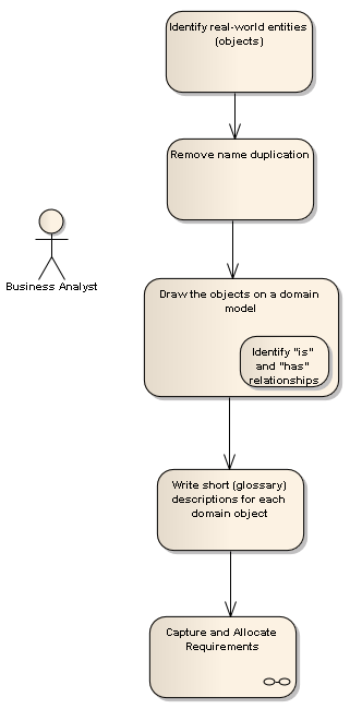
Figure 4. Modeling the Problem Domain is a critical element of ICONIX
Business Process Modeling
Figure
5. Example of a domain model.
Modeling the Business Scenarios
Modeling
Business Process Scenarios represents the bulk of the Business Analyst activity
specified by our roadmap. We first decompose the business into subsystems (functionally related areas) and show this decomposition on UML package
diagrams.
Within
each subsystem, we identify the business scenarios as stereotyped
use cases on UML use case diagrams. As with software scenarios, each business
scenario is written in English, and will typically contain both a sunny-day (basic course of action) and a rainy-day (alternate
courses of action) section.
It
often makes sense to capture both as-is (existing state) and to-be (future
state) business processes. While our roadmap shows the path for future
scenarios, the same steps can easily be used for modeling as-is scenarios,
which would logically precede the modeling of future scenarios.
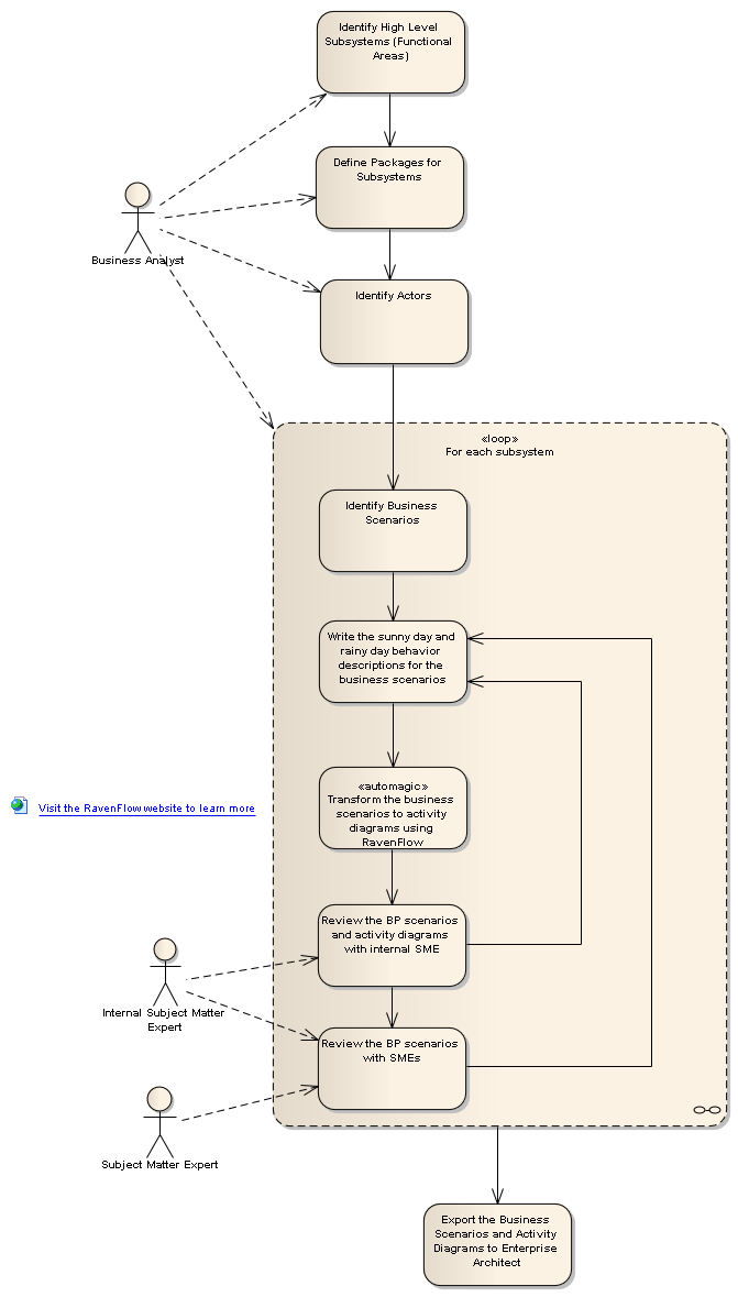
Figure 6. Business Process
Scenarios are identified and documented, requirements are allocated and traced,
and the scenarios are elaborated using Activity Diagrams to expose errors.
After
the business scenarios have been identified and documented in English, they are
linked to Requirements that have been identified earlier in the process.
Typically additional requirements are identified and captured during this
process.
Once
the scenarios have been captured, it's generally advisable to elaborate
them in diagrammatic form, as (similarly to software scenarios) the act
of elaborating a scenario by drawing a picture of it tends to expose errors and
inconsistencies. Our business modeling roadmap specifies the use of UML
Activity Diagrams for this purpose, whereas the ICONIX software roadmap uses
robustness diagrams. There are several reasons for the choice of activity
diagrams as opposed to robustness diagrams, including:
In
Version 1 of the Roadmap, Activity Diagrams were drawn by hand using a UML modeling
tool like Enterprise Architect. Version 2 of the Roadmap incorporates an advance in tools technology
– specifically, Raven’s ability to automatically generate activity
diagrams from a natural language English description of the business scenario.
Figure
7. Raven generates UML Activity
Diagrams automatically from natural language scenarios
There
are numerous advantages to generating Activity Diagrams from scenario
descriptions as opposed to drawing them manually. These include:
Our experience working with business modeling
clients indicates that these are real and important issues which can have a
dramatic effect on the outcome of a BPR project. The Virginia DMV project mentioned at the beginning of this
article, for example, has over 3,000 activity diagrams in its UML model.
When User Interaction is Involved, Identify Software Use Cases and
proceed with System Design
For
those portions of those business scenarios that will involve user interaction
and use cases, software will be designed using the use-case driven ICONIX Process for Software roadmap. When we have captured and
reviewed all of our business scenarios with subject matter experts, we can
consider moving forward to implement those scenarios.
In
some cases, the future-state business scenarios may be realized by multiple software
systems. These automation opportunities should be systematically identified,
prioritized, and scheduled. For each new system developed, the software
scenarios which realize the business scenarios should be identified and design
should proceed following the normal ICONIX
Process for Software Roadmap. Note that the requirements identified during
the business modeling activities should once again be allocated and traced to
and from the software use cases.
Model complex business rules and
generate “business rule enforcement” code.
But
some parts of these applications (generally the “back-ends” of the use cases)
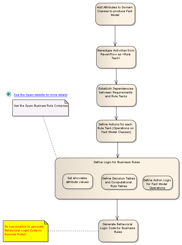
will be largely created in order to enforce business rules. As a first step in this process, once
the Activity Diagrams have been generated in Raven, they can easily be imported
into Enterprise Architect.
Figure
8. Activity diagrams are
exported from Raven into Enterprise Architect, where Business Rules can be
defined, and code generated.
Once
the activity diagrams are imported, the next step in the process is to define
logic for business rules using the Sparx Business Rule Composer.
Figure
9. The Sparx Business Rule
Composer is used to define logic for Business Rules
The
Business Rule Composer allows logic to be specified for a series of “business
rule” requirements. This logic can
be in the form of decision tables and computational rule tables, and can be
quite complex. A key to the
process is that the logical steps are tied directly to the business rules.
Figure
10. The Sparx Business Rule
Composer defines algorithmic logic for business rules.
The
advantages of linking logic to business rules using the rule composer can be
readily seen by examining the code that Enterprise Architect generates for
these business rules.
Figure
11. Algorithmic code is generated
that is directly traceable to the Business Rules.
Enterprise
Architect generates code in a wide range of languages. The example shown here is Java, but
could just as easily be C# or Visual Basic. The key to note here is that the generated code contains the
logic for each business rule, and the traceability between programming logic
and business requirement is directly visible in the generated code. And there are no errors in translation
or misinterpretation of the business requirements during implementation.
Once
again, our experience working with business modeling projects is that these
advantages, which may seem small, add up to something quite substantial. The Virginia DMV project, for example,
has over 15,000 business rules.
To
summarize, we gain the following advantages:
ICONIX
has over 20 years experience working with software projects of all shapes and
sizes, and our experience indicates that these issues are definitely of
critical importance to development efforts.
Conclusion
Version
1 of the ICONIX Business Modeling Roadmap specified a simple, intuitive, yet
rigorous approach to business modeling and offers a seamless transition to use-case-driven
software design when it becomes time to automate portions of the future state
scenarios.
Version
2 of our Roadmap leverages two new advances in tools technology that, when used
together enable a new process for the development of “rule enforcement” code
that starts with a natural language scenario description and ends up with
automatically generated logic that is directly traceable to the requirements.
For
further questions, contact us.